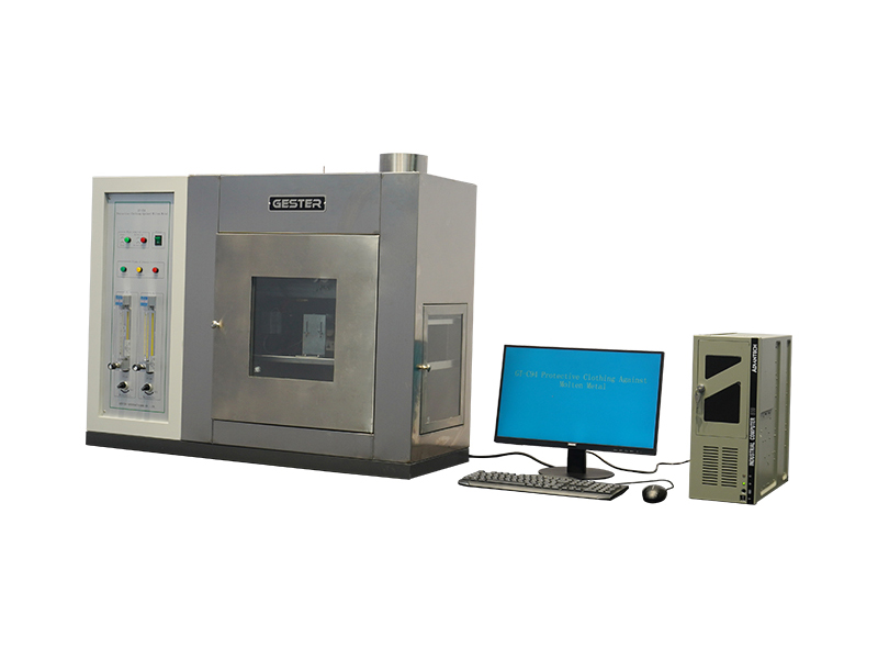
Molten Metal Splash Impact Tester for Protective Clothing GT-C94
Application
The testing machine is used to determine the impact performance of high-temperature metal melt droplets in protective clothing and the high-temperature protection performance of textiles.
Standards
AQ 6103-2007, GB/T 17599, GB/T 8965.2-2009, ISO 9150, EN 348
Features
- Metal droplet generating device
An oxy-acetylene torch is used to melt one end of the metal wire (rod).
The welding nozzle diameter is (1.2 ± 0.1) mm.
The feeding movement of the metal wire (rod) is controlled by a wheel-driven system with motor speed regulation.
The wire feeding rate is (10 ± 1) g/min.
The welding nozzle center is vertically aligned with the wire (rod).
The distance between the welding nozzle and the wire (rod) is adjustable and is typically set to 12 mm.
Droplet mass: (0.50 ± 0.05) g.
Droplet generation frequency: 20 drops/min (± 3 s).
Adjustable starting distance between the wire and the welding burner.
Adjustable length of the deep-blue flame core of the welding torch.
- Droplet guide mechanism
Funnel guide
The angle between the guide axis and the vertical direction is adjustable.
The guide aperture allows passage of a metal strip with a diameter of (8 ± 0.2) mm.
A protective cover is installed on the guide slot to close it when not in use.
Holder
Supports both the bearing and the funnel guide, with full three-dimensional adjustment.
- Temperature sensing system
Sensor support
Made of refractory insulation material with a thermal conductivity of
(0.125 ± 0.015) W/(m·K) and a specific heat capacity of 1.15 J/(g·K).
The surface groove dimensions are (13.5 × 11) mm at 40 °C.
Temperature sensor
Armored platinum resistance thermometer (Pt100), coated with high-temperature adhesive.
Resistance: 100 Ω
Shape: clitheroform.
Dimensions: (12.5 × 10) mm
Thermal response time: ≤ 0.5 s at 0 °C
Recording and display
The system displays the temperature rise on the sample back surface and the corresponding droplet number, time, and frequency.
If the guide slot test temperature exceeds 250 °C, or the temperature rise on the sample back reaches ≥ 40 K, an alarm is triggered.
Accuracy
Temperature resolution: ≤ ±0.5 K
Deviation between temperature display and alarm triggering: ≤ ±0.4 K
Structure and installation
The temperature sensor contacts the sample near the groove center along the guide line of two adjacent holes.
The sensor support is fixed to the sample frame using four side bolts.
- Sample frame
The sample holder ensures close contact between the sample and the temperature sensor.
A pre-tension load of (175 ± 5) g is applied to the sample.
The sample position is adjustable in both vertical and horizontal directions.
- Software
The instrument is equipped with professional computer software for data acquisition, display, and analysis.
- Gas supply
Oxygen and acetylene gases are not included and must be purchased locally by the user.