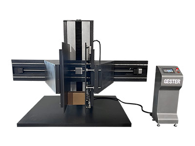
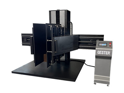

Application
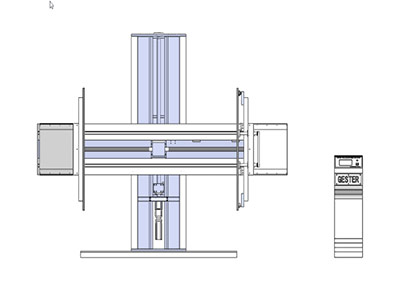
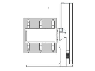
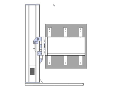
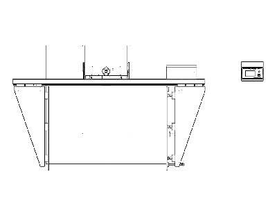
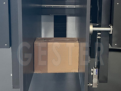
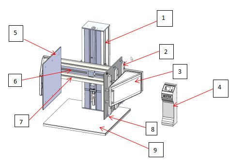
This equipment simulates the clamping conditions that occur when a clamp truck loads and unloads packaged goods. By reproducing the clamping force applied between two plywood plates, it is used to test and evaluate the clamping strength and protection performance of the package and its contents.
| Model | |
| Max. capacity | 400–3000 lb |
| Max. specimen weight | 600 kg (customizable) |
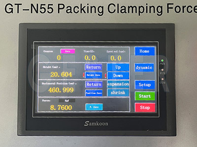
| Controller | 7-inch touch screen |
| Sensors | 6 units |
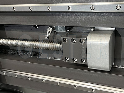
| Drive system | Servo motor with DC variable-speed drive and high-precision ball screw |
| Force unit | kgf / N / lbf (selectable) |
| Sensor accuracy | 1/250,000 |
| Load accuracy | within ±0.25% |
| Smoothness (movement accuracy) | within ±2.5 mm |
| Sensor resolution | 1/250,000 |
| Clamping plate size | Height 48 in, depth 48 in |
| Clamp plate adjustable height | 0–1000 mm |
| Clamp plate adjustable width | 200–2000 mm |
| Base plate size | 2200 × 2100 mm |
| Test speed | 0.25–2.5 mm/s (in accordance with ISTA 6 – SAM’S CLUB) |
| Software | Proprietary system (independent R&D) |
| Data display | Load, displacement, speed, loading rate, elapsed time |
| Functions | Clamp plates can move up and down |
| Clamping plate requirements | Plates remain flat and deformation-free under 2000 lb; plates parallel and perpendicular to the base; thickness ≥ 25 mm |
| Safety features | Emergency stop; overload protection; upper and lower limit switches; load sensor with automatic return |
| Displacement & lifting speed | Computer-controlled; adjustable 0–1200 mm; displacement accuracy verified by scale |
| Maximum allowable specimen height | 2.2 m + 1.2 m lifting stroke; overall equipment height approx. 2.8 m |
| Packing volume | 11.2 CBM |
| Gross weight | 1000 kg |
| Power supply | Single-phase AC 220 V ±10%, 50/60 Hz (other voltages on request) |